|
This tutorial is intended to demonstrate the sequence of actions
required to detect Caulobacter crescentus cells in timelapses with the
help of MicrobeTracker, to obtain
fluorescence profiles, and to use MATLAB for their analysis (the last task
requires some previous MATLAB knowledge). For a more general description of the
cell detection procedure and other steps of MicrobeTracker operation see the
MicrobeTracker Protocols section,
for the full list of tutorials see Quick Start
section of the help. This tutorial assumes that the
installation procedure has been
already performed as described.
The data for this tutorial is not available by default because of its large
size (about 50 MB). Please, make sure you download the version of MicrobeTracker
that contains all tutorials from the
MicrobeTracker website.
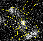
The images are C. crescentus cells expressing MipZ-YFP protein from
the endogenous MipZ promoter. The images were taken at 1.5 min intervals at
0.064 µm/pixel resolution. See
Schofield
WB et al., EMBO J, 2010 paper for the details of this experiment.
This tutorial shows how to orient cells, obtain the averaged fluoresncence
profile of these cells, and find the position of its minimum.
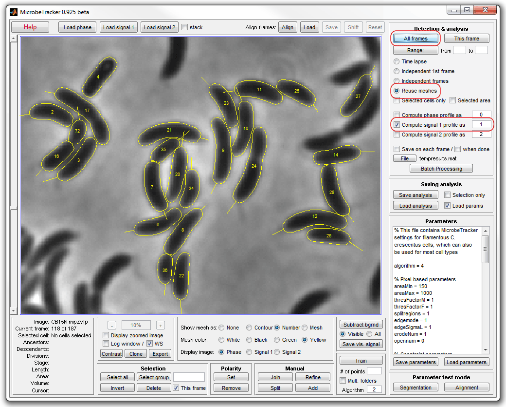
1. Start MATLAB. Set the working path in MATLAB to the folder of the
example: ...\MicrobeTracker...\examples\microbetracker_ccres_fluo
(see the image below, click on the image for its full resolution version).

2. Type microbeTracker in MATLAB's command
window to start MicrobeTracker. A new MicrobeTracker window will open.
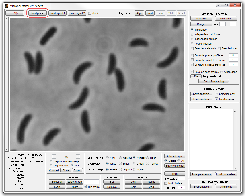
Click Load phase and select the phase_contrast
subfolder of the example folder to load the images.
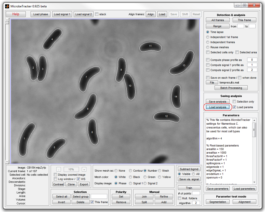
3. In this tutorial you should simply load saved meshes by clicking
Load analysis and selection the file meshes.set
from the example folder. If you wish, you can repeat the detection by loading
parameters from the same file (make sure you change the file extension from .set
to .mat in the file opening dialog).
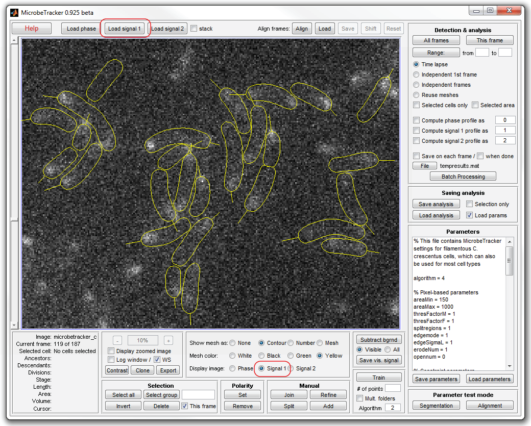
4. Load fluorescence images by clicking the Load signal 1
button from the Detection & analysis panel. Inspect the images by
selecting the Signal 1 checkbox. Select yellow or green cell outlines for
better visibility.
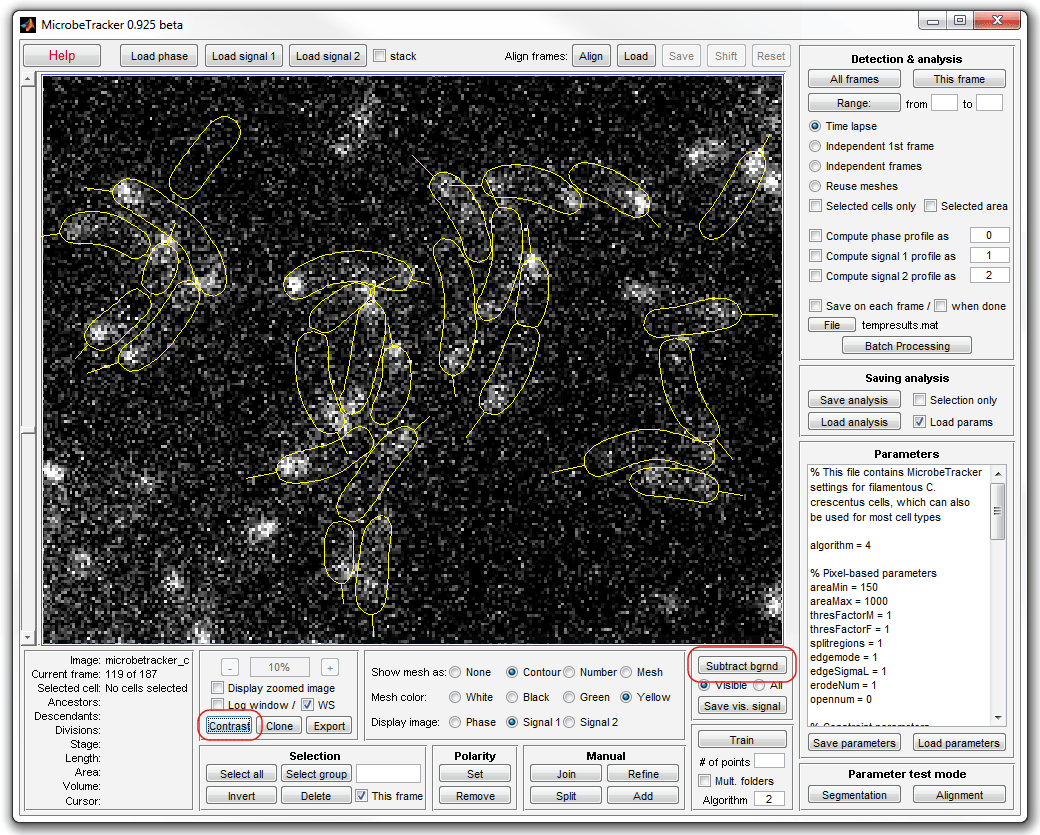
5. Subtract the background by clicking Subtract bgrnd (make
sure that the fluorescence images are currently displayed, otherwise select
All on the signal subtraction panel). Click Contrast to adjust
the contrast of the images (exclusively for better visibitily, this step does
not affect the results).
6. Add signal profiles to the meshes. Uncheck Save on each frame
chackbox on the Detection & analysis panel to not save the results on
each frame (which takes time). Select Reuse meshes radiobutton,
Compute signal 1 profile checkbox, and click the All frames
button to start processing.
7. Save the cell meshes by clicking Save analysis (the included
file meshes.mat already contains the predetected profiles, so this step can be skipped).
Load this file into the MATLAB command window by dragging and dropping or by
typing the name of the file (the .mat extension can be dropped; if the file is
in the current MATLAB folder, the full path can be dropped as well; the input
text here and below will be shown in blue color to distinguish it from MATLAB
output, which is shown in black):
load('meshes')
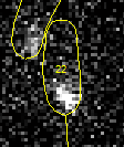
8. Do not close MicrobeTracker. Pick a cell in the MicrobeTracker window
to look at. Let it be cell 22 on frame 100.
To display its profile type (the figure command
creates a new figure, otherwise the following command will replot the MicrobeTracker window):
figure
plot(cellList{100}{22}.signal1)
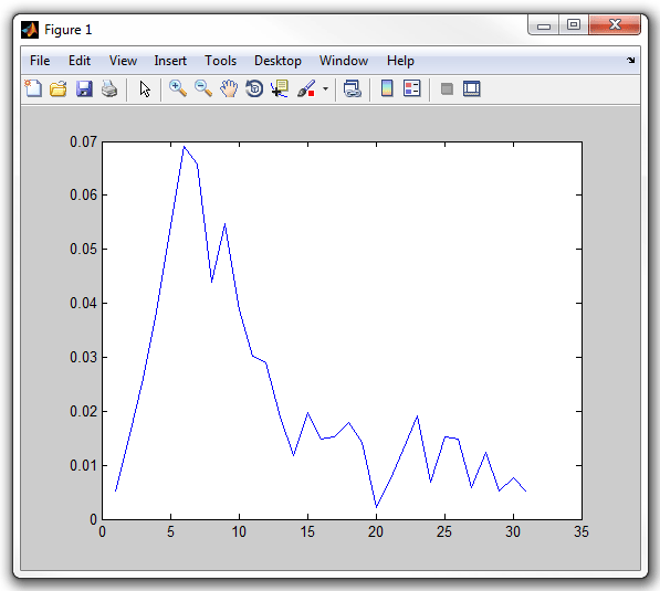
Notice that the cell has a little straight "stalk" sticking from a pole.
This "stalk" indicates the old pole of the cell when it is known (either because
this cell resulted from a division in this time-lapse series or because the polarity of
the cell was set manually). When this stalk is present, the signal profile data
is oriented from the old to the new pole (if it is not present, the orientation
is random). Therefore, the left of the plot corresponds to the bottom of the
image. Indeed, the intensity on the plot is higher on the left, which
corresponds to the bright spot on the bottom of the cell.
9. This and the following sections are intended to learn how to write
simeple scripts in MATLAB to process tha data and require some MATLAB knowledge.
Now count how many unique cell-frame combinations we have, i.e. sum the number
of frames each cell has been in the time-lapse series for. To do so, we cycle
though all the frames and through all cells withing each frame, and only look at
those where the cell is present.
counter=0;
for frame=1:length(cellList)
for cell=1:length(cellList{frame})
if ~isempty(cellList{frame}{cell})
counter=counter+1;
end
end
end
counter
counter =
4395
I.e. the number of unique cell-frame combinations is 4395.
10. Now count the number of cell division events by counting the cells
immediately after a division, and only those that are not "newborn". Here the
divisions field of the cell structure contatins the
list of frames on which the cell divided. We make sure the cell did divide and that the
last division was on this frame. The field descendants
holds the list of daughter cells, here we make sure it is empty, meaning that we are
looking at the "mother" cell, i.e. the old pole cell when the orientation is
known or a random of the two daughter cells when it is not.
counter=0;
for frame=2:length(cellList)
for cell=1:length(cellList{frame})
if ~isempty(cellList{frame}{cell})
if ~isempty(cellList{frame}{cell}.divisions) && ...
cellList{frame}{cell}.divisions(end)==frame && ...
~isempty(cellList{frame}{cell}.descendants)
counter=counter+1;
end
end
end
end
counter
counter =
17
I.e. there are 17 division events in this time-lapse series.
11. Now look at the cell which just divided and for which the
orientation of the cells before the division is known. For these cells
display the intensity profiles before the division in separate windows:
for frame=2:length(cellList)
for cell=1:length(cellList{frame})
if ~isempty(cellList{frame}{cell})
if ~isempty(cellList{frame}{cell}.divisions) && ...
cellList{frame}{cell}.divisions(end)==frame && ...
~isempty(cellList{frame}{cell}.descendants) && ...
cellList{frame-1}{cell}.polarity
figure
plot(cellList{frame-1}{cell}.signal1)
end
end
end
end
MATLAB will display 6 figures.
12. These profiles represent the integrated signal inside of each
segment. To represent the average pixel intensity inside of each segment we
need to divide the integrated signal by the area of each segment. Notice,
that at the division a dot is used before the division sign, which indicates
that the division needs to be performed elementwise, rather than being a matrix
division:
for frame=2:length(cellList)
for cell=1:length(cellList{frame})
if ~isempty(cellList{frame}{cell})
if ~isempty(cellList{frame}{cell}.divisions) && ...
cellList{frame}{cell}.divisions(end)==frame && ...
~isempty(cellList{frame}{cell}.descendants) && ...
cellList{frame-1}{cell}.polarity
figure
plot(cellList{frame-1}{cell}.signal1./cellList{frame-1}{cell}.steparea)
end
end
end
end
MATLAB will display 6 figures.
13. The plots are very noisy because of low light level
and therefore shot noise of detection. To deal with that we collect the data
from the previous 10 frames to obtain an averaged profile. A complexity arises
because the number of segments in each cell increases as the cell grows.
Therefore, we interpolate the intensity at 51 points spread uniformly from one
pole of the cell to the other. In addition we smooth the resulting profile and
collect the data for each cell in a matrix of 6 rows (for 6 division events) and
51 columns. Since the script is becoming long, it is saved as
mipzprofile1.m in the example folder. To run the
script, type mipzprofile1 in MATLAB command window.
To see it, type edit mipzprofile1. The script will
open in MATLAB editor. Alternatively, you can open the editor and load the file
through File>Open menu command.
14. After you run the script, display the profiles on a single graph
with the x-axis spanning from 0 (old cell pole) to 1 (new cell pole):
xvector = 0:1/50:1;
figure
plot(xvector,profilearray')
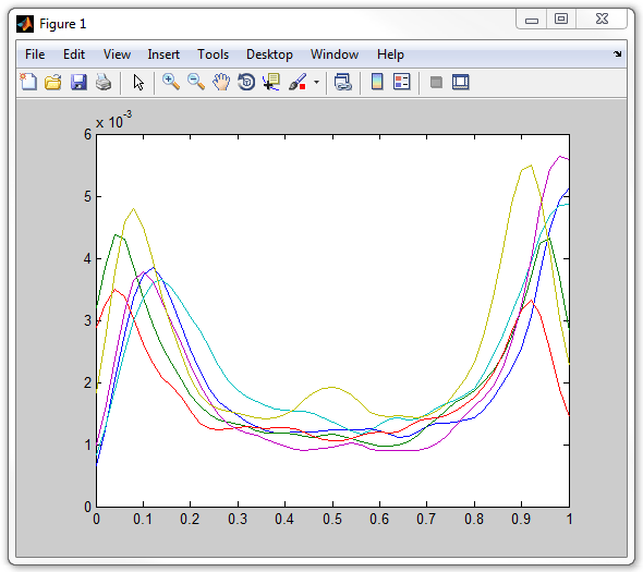
Notice that one of the profiles has a distinct "bump" in the middle, unlike
the rest of them. This is suspicious and could be caused by an artifact,
therfore we should inspect this cell to examine this possibility. To see
which cell this is, select Insert>Legend
from the figure menu. A figure legend appears, from which it is clear that the
profile with the bump corresponds to the sixth cell.
15. Now we want to find the number and the frame this cell. To do so,
we add a line to the script that would display the frame and cell number for each
division event. In order to convert numbers to strings, we use MATLAB's
num2str command. A string that you enter in MATLAB
directly has to be enclosed into single quotes. The resulting short strings are
concatenated (joined together) with the help of []
operator. And finally the disp command is used to
display the resulting string. The whole line in the script looks like (don't
run it alone):
disp(['Event ' num2str(count) ': frame=' num2str(frame) ', cell=' num2str(cell)])
Run the modified version of the previous script with this line inserted,
which is called mipzprofile2. The program will
display:
Event 1, frame =100, cell=6
Event 2: frame=112, cell=7
Event 3: frame=116, cell=8
Event 4: frame=118, cell=16
Event 5: frame=119, cell=24
Event 6: frame=124, cell=17
16. Now we know that the sixth cell corresponds to the cell number 17 on frames
114-123 (the frame 124 displayed is the frame after the division, whilest we
look at the profiles on 10 preceeding frames). Inspect this cell in
MicrobeTracker by scrolling to frame 123 and finding cell 17 (to find it faster,
type "17" in the editbox on Selection panel and click Group on
that panel.
The reason for the bump in the intensity profile in the middle of the cell is
now obvious and is caused by closely located cell 72. The signal from that cell
partially penetrates into the outline of cell 17 because of diffraction. This
example demonstrates a drawback of working with fluorescence with closely packed
cells, unfortunately in this case the problem is unavoidable: since we are
looking at cells after 1-2 divisions, touching cell are will be present. Therefore,
all we can do is to eliminaate this cell from our future analysis. We know that
we have profiles of six cells and this cell in the last one. To get the portion
of the profile matrix without the last line use the command (don't enter it now):
profilearray(1:5,:)
Here the profilearray is indexed with two
indices, the first corresponds to the rows and the second to columns. The
notation 1:5 give you all integer numbers from 1 to
5, and the notation : standing alone means "all
elements of the array". Therefore, by using this command we are chopping the
matrix, leaving only first five rows of it.
17. To calculate the mean profile for all 5 cells type:
meanprofile = mean(profilearray(1:5,:));
18. Now we want to find the position of the minimum intensity of the profile
excluding the poles. To do so, we first find the local maxima (which are present
at the poles) and then the global minimum between the first and the last local
maxima. To find the local maxima we compare each pixel with its two neighbors:
meanprofile>meanprofile([2 1:end-1])&meanprofile>meanprofile([2:end end-1])
We obtain a string of 1,s and 0,s for each element, with a 1 indicating that
it the value is larger than the neighbor values. After which we use MATLAB's
find command to find non-zero elements of the array.
To get these numbers type:
mx = find(meanprofile>meanprofile([2 1:end-1])&meanprofile>meanprofile([2:end end-1]));
To find the global minimum in between first chop the array by keeping only
the part between the maxima, then use MATLAB's min
command and increment the index of the minimum so that is corresponds to the
original non-chopped array:
[mnv,mn] = min(meanprofile(mx(1):mx(end)));
mn = mn+mx(1)-1
mn =
30
I.e. the position of the minumum is point 30, which is at 30/50=60% of cell
length, demonstrating asymmetry in the profile.
19. Plot the averaged profile and the positions of the maxima (in
green)and the minimum (in red):
figure
plot(xvector,meanprofile,'-',xvector(mx),meanprofile(mx),'.',xvector(mn),meanprofile(mn),'.')
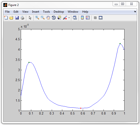
The final script for this analysis is saved as mipzprofile3.m in the example folder.
|